


| Model | HDM3075H | HDM3075B | HDM3075A | HDM3075S | HDM3075 |
| Resolution bit | 7 1/2 | 7 1/2 | 7 1/2 | 7 1/2 | 7 1/2 |
| DCV basic precision | 16 ppm | 16 ppm | 16 ppm | 16 ppm | 16 ppm |
| Maximum reading rate | 50,000 rdgs/s | 50,000 rdgs/s | 50,000 rdgs/s | 50,000 rdgs/s | 50,000 rdgs/s |
| Memory | 10,000 readings | 10,000 readings | 10,000 readings | 10,000 readings | 10,000 readings |
|
Dual-display measurement function |
√ | √ | √ | √ | √ |
| Statistical graph |
Histogram, bar graph, trend graph |
Histogram, bar graph, trend graph |
Histogram, bar graph, trend graph |
Histogram, bar graph, trend graph |
Histogram, bar graph, trend graph |
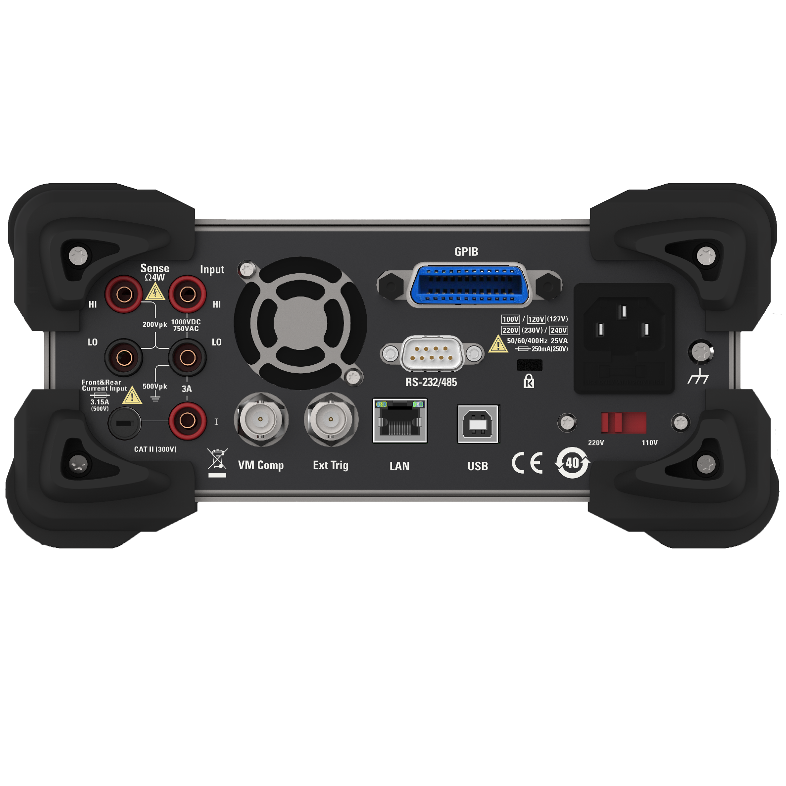
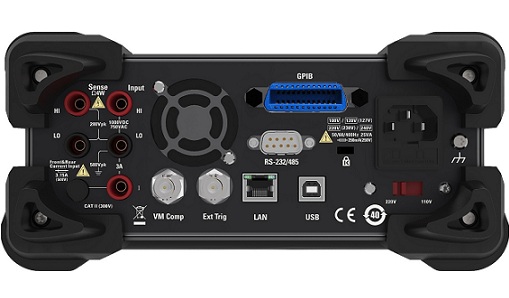
| Interface | USB, RS232/485, LAN, GPIB | USB, RS232/485, LAN | USB, RS232/485 | USB, RS232/485 | USB, RS232/485 |
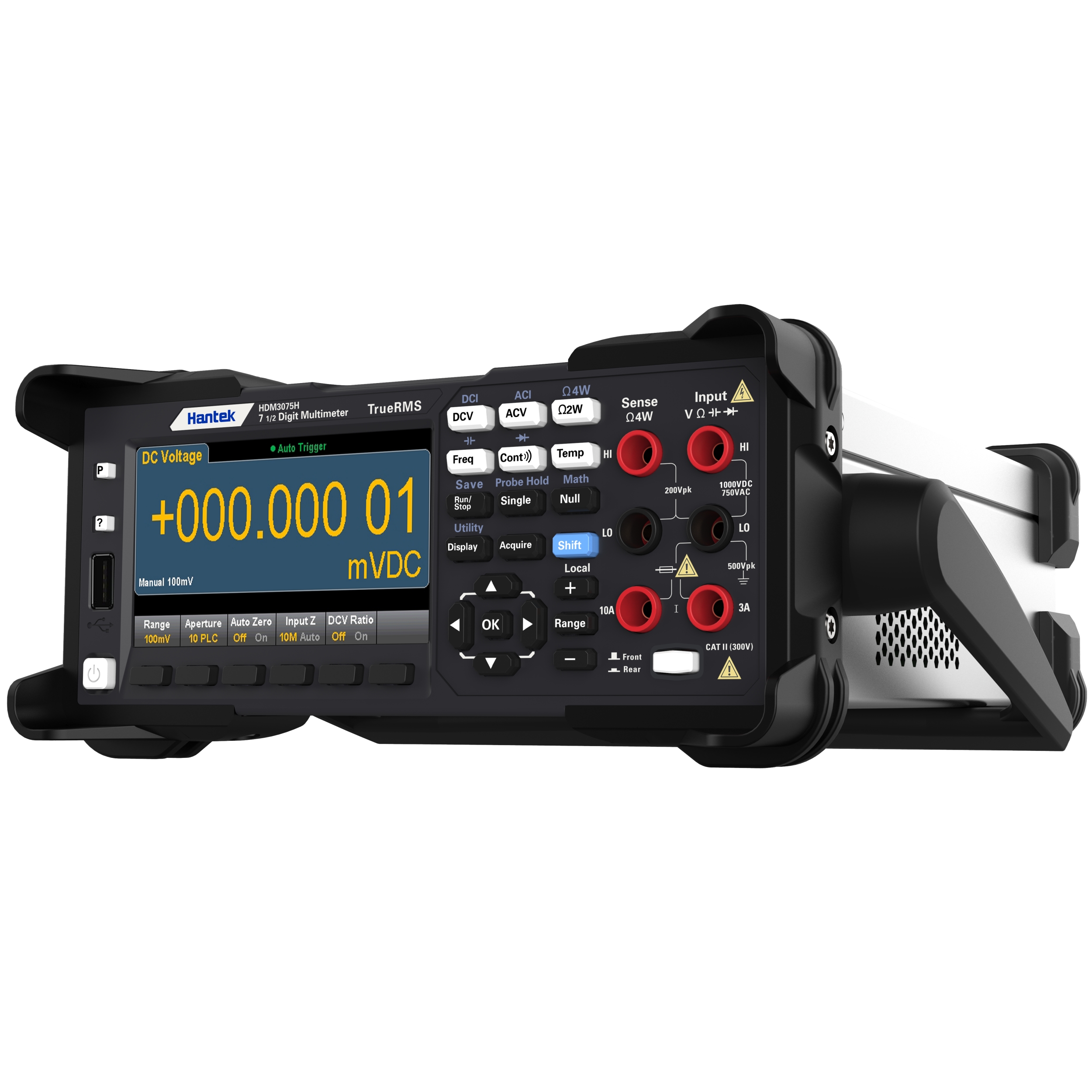
| Input terminal | Front-panel, Rear-panel | Front-panel, Rear-panel | Front-panel, Rear-panel | Rear-panel | Front-panel |
| Range(2) | 24 Hours(3) | 90 Days | 1 Year | 2 Years |
Temperature coefficient/ ℃(6) |
| Tcal ± 1℃ | Tcal ± 5℃ | Tcal ± 5℃ | Tcal ± 5℃ | ||
| DC Voltage | |||||
| 100mV | 0.0030 + 0.0030 | 0.0040 + 0.0035 | 0.0040 + 0.0035 | 0.0045 + 0.0035 | 0.0005 + 0.0005 |
| 1V | 0.0010 + 0.0004 | 0.0015 + 0.0004 | 0.0020 + 0.0004 | 0.0025 + 0.0004 | 0.0005 + 0.0001 |
| 10V | 0.0008 + 0.0002 | 0.0013 + 0.0002 | 0.0016 + 0.0002 | 0.0020 + 0.0002 | 0.0005 + 0.0001 |
| 100V | 0.0020 + 0.0006 | 0.0032 + 0.0006 | 0.0038 + 0.0006 | 0.0040 + 0.0006 | 0.0005 + 0.0001 |
| 1000V(10) | 0.0020 + 0.0006 | 0.0032 + 0.0006 | 0.0038 + 0.0006 | 0.0040 + 0.0006 | 0.0005 + 0.0001 |
| Resistance(9) | |||||
| 100Ω | 0.0030 + 0.0030 | 0.008 + 0.004 | 0.010 + 0.004 | 0.012 + 0.004 | 0.0006 + 0.0005 |
| 1KΩ | 0.0020 + 0.0005 | 0.008 + 0.001 | 0.010 + 0.001 | 0.012 + 0.001 | 0.0006 + 0.0001 |
| 10KΩ | 0.0020 + 0.0005 | 0.008 + 0.001 | 0.010 + 0.001 | 0.012 + 0.001 | 0.0006 + 0.0001 |
| 100KΩ | 0.0020 + 0.0005 | 0.008 + 0.001 | 0.010 + 0.001 | 0.012 + 0.001 | 0.0006 + 0.0001 |
| 1MΩ | 0.002 + 0.001 | 0.008 + 0.001 | 0.010 + 0.001 | 0.012 + 0.001 | 0.0010 + 0.0002 |
| 10MΩ | 0.015 + 0.001 | 0.020 + 0.001 | 0.040 + 0.001 | 0.060 + 0.001 | 0.0030 + 0.0004 |
| 100MΩ | 0.300 + 0.010 | 0.800 + 0.010 | 0.800 + 0.010 | 0.800 + 0.010 | 0.1500 + 0.0002 |
| DC Current | |||||
| 1μA(4,7) | 0.700 + 0.010 | 3.000 + 0.010 | 5.000 + 0.010 | 6.000 + 0.010 | 0.2000 + 0.0020 |
| 1μA(4,8) | 0.070 + 0.005 | 0.300 + 0.005 | 0.500 + 0.005 | 0.600 + 0.005 | 0.0020 + 0.0010 |
| 10μA(4) | 0.007 + 0.002 | 0.030 + 0.002 | 0.050 + 0.002 | 0.060 + 0.002 | 0.0015 + 0.0006 |
| 100μA(4) | 0.007 + 0.001 | 0.030 + 0.001 | 0.050 + 0.001 | 0.060 + 0.001 | 0.0015 + 0.0004 |
| 1mA | 0.007 + 0.003 | 0.030 + 0.005 | 0.050 + 0.005 | 0.060 + 0.005 | 0.0015 + 0.0005 |
| 10mA | 0.007 + 0.020 | 0.030 + 0.020 | 0.050 + 0.002 | 0.060 + 0.002 | 0.0020 + 0.0020 |
| 100mA | 0.010 + 0.004 | 0.030 + 0.005 | 0.050 + 0.005 | 0.060 + 0.005 | 0.0020 + 0.0005 |
| 1A | 0.050 + 0.006 | 0.070 + 0.010 | 0.080 + 0.010 | 0.100 + 0.010 | 0.0050 + 0.0010 |
| 3A | 0.180 + 0.020 | 0.200 + 0.020 | 0.200 + 0.020 | 0.230 + 0.020 | 0.0050 + 0.0020 |
| 10A(5) | 0.050 + 0.010 | 0.120 + 0.010 | 0.120 + 0.010 | 0.150 + 0.010 | 0.0050 + 0.0010 |
| Continuity | |||||
| 1KΩ | 0.002 + 0.030 | 0.008 + 0.030 | 0.010 + 0.030 | 0.012 + 0.030 | 0.0010 + 0.0020 |
| Diode Testing(11) | |||||
| 5V | 0.002 + 0.030 | 0.008 + 0.030 | 0.010 + 0.030 | 0.012 + 0.030 | 0.0010 + 0.0020 |
| Temperature | |||||
| PT100 (DIN/IEC 751)(12) | The probe accuracy + 0.05 ℃ | ||||
| 5KΩThermistor | The probe accuracy + 0.10 ℃ | ||||
| True RMS AC voltage(13,14) | |||||
| 100mV, 1V, 10V, 100V, 750V range | |||||
| 3-5Hz | 0.50 + 0.02 | 0.50 + 0.02 | 0.50 + 0.02 | 0.50 + 0.02 | 0.010 + 0.003 |
| 5-10Hz | 0.10 + 0.02 | 0.10 + 0.02 | 0.10 + 0.02 | 0.11 + 0.02 | 0.008 + 0.003 |
| 10Hz-20KHz | 0.02 + 0.02 | 0.04 + 0.02 | 0.05 + 0.02 | 0.06 + 0.02 | 0.007 + 0.003 |
| 20-50KHz | 0.05 + 0.03 | 0.06 + 0.03 | 0.07 + 0.03 | 0.08+ 0.03 | 0.010 + 0.005 |
| 50-100KHz | 0.15 + 0.05 | 0.15 + 0.05 | 0.15 + 0.05 | 0.15 + 0.05 | 0.060 + 0.008 |
| 100-300KHz | 1.00 + 0.10 | 1.00 + 0.10 | 1.00 + 0.10 | 1.00 + 0.10 | 0.200 + 0.020 |
| True RMS AC current(14,15) | |||||
| 10μA range | |||||
| 3Hz-5KHz | 0.35 + 0.04 | 0.40 + 0.04 | 0.40 + 0.04 | 0.055 + 0.006 | |
| 5-10KHz(4) | 0.35 + 0.04 | 0.40 + 0.04 | 0.40 + 0.04 | 0.055 + 0.006 | |
| 100μA, 1mA, 10mA, 100mA, 1A range | |||||
| 3Hz-5KHz | 0.07 + 0.04 | 0.09 + 0.04 | 0.10 + 0.04 | 0.10 + 0.04 | 0.015 + 0.006 |
| 5-10KHz(4) | 0.10 + 0.04 | 0.10 + 0.04 | 0.10 + 0.04 | 0.10 + 0.04 | 0.030 + 0.006 |
| 3A range | |||||
| 3Hz-5KHz | 0.23 + 0.04 | 0.23 + 0.04 | 0.23 + 0.04 | 0.23 + 0.04 | 0.015 + 0.006 |
| 5-10KHz(4) | 0.23 + 0.04 | 0.23 + 0.04 | 0.23 + 0.04 | 0.23 + 0.04 | 0.030 + 0.006 |
| 10A range(5) | |||||
| 3Hz-5KHz | 0.10 + 0.04 | 0.15 + 0.04 | 0.15 + 0.04 | 0.15 + 0.04 | 0.015 + 0.006 |
| 5-10KHz(4) | 0.15 + 0.04 | 0.15 + 0.04 | 0.15 + 0.04 | 0.15 + 0.04 | 0.030 + 0.006 |
| Capacitance(19) | |||||
| 1.0000nF | 0.50 + 0.50 | 0.50 + 0.50 | 0.50 + 0.50 | 0.50 + 0.50 | 0.05 + 0.05 |
| 10.000nF | 0.40 + 0.10 | 0.40 + 0.10 | 0.40 + 0.10 | 0.40 + 0.10 | 0.05 + 0.01 |
| 100.00nF | 0.40 + 0.10 | 0.40 + 0.10 | 0.40 + 0.10 | 0.40 + 0.10 | 0.05 + 0.01 |
| 1.0000μF | 0.40 + 0.10 | 0.40 + 0.10 | 0.40 + 0.10 | 0.40 + 0.10 | 0.05 + 0.01 |
| 10.000μF | 0.40 + 0.10 | 0.40 + 0.10 | 0.40 + 0.10 | 0.40 + 0.10 | 0.05 + 0.01 |
| 100.00μF | 0.40 + 0.10 | 0.40 + 0.10 | 0.40 + 0.10 | 0.40 + 0.10 | 0.05 + 0.01 |
| Frequency (16,18) | |||||
| 100mV, 1V, 10V, 100V, 750V range(18) | |||||
| 3-40Hz | 0.070 | 0.070 | 0.070 | 0.070 | 0.035 |
| 40-100Hz | 0.030 | 0.030 | 0.030 | 0.030 | 0.035 |
| 100Hz-1KHz | 0.003 | 0.006 | 0.007 | 0.010 | 0.015 |
| 1-300KHz | 0.002 | 0.005 | 0.007 | 0.009 | 0.015 |
| square wave(15) | 0.001 | 0.004 | 0.006 | 0.008 | 0.015 |
| Additional frequency errors ± (% of reading)(16) | |||||
| Aperture (Resolution/Range) | 1 second(0.1 ppm) | 0.1 seconds(1 ppm) | 0.01 seconds(10 ppm) | ||
| 3-40Hz | 0 | 0.200 | 0.200 | ||
| 40-100Hz | 0 | 0.060 | 0.200 | ||
| 100Hz-1KHz | 0 | 0.020 | 0.200 | ||
| 1-300KHz | 0 | 0.004 | 0.030 | ||
| square wave(17) | 0 | 0.000 | 0.000 | ||
| DC current burden voltage at full scale | |||||
| DC current range | Burden voltage | ||||
| 1μA | <0.11V | ||||
| 10μA | <0.11V | ||||
| 100μA | <0.11V | ||||
| 1mA | <0.11V | ||||
| 10mA | <0.11V | ||||
| 100mA | <0.11V | ||||
| 1A | <0.11V | ||||
| 3A | <0.33V | ||||
| 10A | <0.11V | ||||
1. The specifications are effective after 60 minutes of warm up, with an integration time set to 10 or 100 NPLC, and using an AC slow filter.
2. Except for 1000 DCV, 750 ACV, 10 DCA, 3 DCA, 10 ACA, 3 ACA, and diode testing (0%), all ranges have a 20% over range.
3.Relative to standard calibration.
4.These specifications are typical performance.
5.The 10A range is only available on the front panel connector.
6. Add a coefficient for every 1 degree (° C) outside the TCAL ± 5 ° C.
7. The DCI input value is within the range of ≥ 0 and ≤+20%, The DCI input value is within the range of ≤ 0 and ≥ -20% Range.
8. DCI input values are in the range other than "7".
9. The specifications are applicable to 4-wire or 2-wire measurement (calculation bias zeroing) resistance measurement. If there is no mathematical null value, 2-wire resistance measurement will add an additional error of 0.2 Ω.
10. When the voltage exceeds ± 500 VDC, an error of 0.02 mV increases every 1V.
11. The specifications are applicable to the voltage measured at the input terminal. The 1 mA test current is a typical value. The variation of the current source will cause a change in the voltage drop at the diode junction.
12. The selected probe will limit the actual measurement range and detection error. The probe accuracy includes all measurement and ITS-90 temperature conversion errors. PT100 can be set to 100 Ω± 5 Ω to eliminate the original probe error.
13. Specifications: When the input sine wave frequency is ≤ 100KHz, Effective when the sine wave input from 100mV Range to 100V Range is greater than 3% of the range, Effective when 750V Range sine wave input>5% range;
When the input sine wave frequency is greater than 100KHz and ≤ 300KHz, it is effective when the sine wave input is greater than 8% of the range.
Within all frequency bands, when exceeding 300 Vrms, the error increases by 1 mVrms for every 1V.
14. Low frequency performance: Provides three filter settings: 3 Hz, 20 Hz, 200 Hz. The frequency has been specified to be greater than the settings of these filters and will not generate additional errors.
15. The specifications are effective when the AC current input is greater than 1% of the range and greater than 9 μArms.
16. Unless otherwise specified, specifications are valid when the instrument has a sine wave input.
17. The square wave input is specified as 10-300 kHz on a 1-second aperture. When the aperture is smaller, the minimum frequency requirement is greater than 2 cycles.
18. Input>100 mV. For 10 mV to 100 mV inputs, multiply the reading error% by 10. The amplitude range is 10-120%, but it is 14-100% in the 750 ACV range. The specifications are applicable for a 1-second gating time (7-digit).
19. Specifications are applicable to situations where mathematical null values are used to reset to zero. Capacitors with high dissipation factors may display different results compared to single frequency measurements. The dissipation factor of thin film capacitors is usually lower than that of other dielectric materials.
| Range(2) | 24 Hours(3) | 90 Days | 1 Year | 2 Years |
Temperature coefficient/ ℃(6) |
| Tcal ± 1℃ | Tcal ± 5℃ | Tcal ± 5℃ | Tcal ± 5℃ | ||
| DC Voltage | |||||
| 100mV | 0.0030 + 0.0030 | 0.0040 + 0.0035 | 0.0040 + 0.0035 | 0.0045 + 0.0035 | 0.0005 + 0.0005 |
| 1V | 0.0010 + 0.0004 | 0.0015 + 0.0004 | 0.0020 + 0.0004 | 0.0025 + 0.0004 | 0.0005 + 0.0001 |
| 10V | 0.0008 + 0.0002 | 0.0013 + 0.0002 | 0.0016 + 0.0002 | 0.0020 + 0.0002 | 0.0005 + 0.0001 |
| 100V | 0.0020 + 0.0006 | 0.0032 + 0.0006 | 0.0038 + 0.0006 | 0.0040 + 0.0006 | 0.0005 + 0.0001 |
| 1000V(10) | 0.0020 + 0.0006 | 0.0032 + 0.0006 | 0.0038 + 0.0006 | 0.0040 + 0.0006 | 0.0005 + 0.0001 |
| Resistance(9) | |||||
| 100Ω | 0.0030 + 0.0030 | 0.008 + 0.004 | 0.010 + 0.004 | 0.012 + 0.004 | 0.0006 + 0.0005 |
| 1KΩ | 0.0020 + 0.0005 | 0.008 + 0.001 | 0.010 + 0.001 | 0.012 + 0.001 | 0.0006 + 0.0001 |
| 10KΩ | 0.0020 + 0.0005 | 0.008 + 0.001 | 0.010 + 0.001 | 0.012 + 0.001 | 0.0006 + 0.0001 |
| 100KΩ | 0.0020 + 0.0005 | 0.008 + 0.001 | 0.010 + 0.001 | 0.012 + 0.001 | 0.0006 + 0.0001 |
| 1MΩ | 0.002 + 0.001 | 0.008 + 0.001 | 0.010 + 0.001 | 0.012 + 0.001 | 0.0010 + 0.0002 |
| 10MΩ | 0.015 + 0.001 | 0.020 + 0.001 | 0.040 + 0.001 | 0.060 + 0.001 | 0.0030 + 0.0004 |
| 100MΩ | 0.300 + 0.010 | 0.800 + 0.010 | 0.800 + 0.010 | 0.800 + 0.010 | 0.1500 + 0.0002 |
| DC Current | |||||
| 1μA(4,7) | 0.700 + 0.010 | 3.000 + 0.010 | 5.000 + 0.010 | 6.000 + 0.010 | 0.2000 + 0.0020 |
| 1μA(4,8) | 0.070 + 0.005 | 0.300 + 0.005 | 0.500 + 0.005 | 0.600 + 0.005 | 0.0020 + 0.0010 |
| 10μA(4) | 0.007 + 0.002 | 0.030 + 0.002 | 0.050 + 0.002 | 0.060 + 0.002 | 0.0015 + 0.0006 |
| 100μA(4) | 0.007 + 0.001 | 0.030 + 0.001 | 0.050 + 0.001 | 0.060 + 0.001 | 0.0015 + 0.0004 |
| 1mA | 0.007 + 0.003 | 0.030 + 0.005 | 0.050 + 0.005 | 0.060 + 0.005 | 0.0015 + 0.0005 |
| 10mA | 0.007 + 0.020 | 0.030 + 0.020 | 0.050 + 0.002 | 0.060 + 0.002 | 0.0020 + 0.0020 |
| 100mA | 0.010 + 0.004 | 0.030 + 0.005 | 0.050 + 0.005 | 0.060 + 0.005 | 0.0020 + 0.0005 |
| 1A | 0.050 + 0.006 | 0.070 + 0.010 | 0.080 + 0.010 | 0.100 + 0.010 | 0.0050 + 0.0010 |
| 3A | 0.180 + 0.020 | 0.200 + 0.020 | 0.200 + 0.020 | 0.230 + 0.020 | 0.0050 + 0.0020 |
| 10A(5) | 0.050 + 0.010 | 0.120 + 0.010 | 0.120 + 0.010 | 0.150 + 0.010 | 0.0050 + 0.0010 |
| Continuity | |||||
| 1KΩ | 0.002 + 0.030 | 0.008 + 0.030 | 0.010 + 0.030 | 0.012 + 0.030 | 0.0010 + 0.0020 |
| Diode Testing(11) | |||||
| 5V | 0.002 + 0.030 | 0.008 + 0.030 | 0.010 + 0.030 | 0.012 + 0.030 | 0.0010 + 0.0020 |
| Temperature | |||||
| PT100 (DIN/IEC 751)(12) | The probe accuracy + 0.05 ℃ | ||||
| 5KΩThermistor | The probe accuracy + 0.10 ℃ | ||||
| True RMS AC voltage(13,14) | |||||
| 100mV, 1V, 10V, 100V, 750V range | |||||
| 3-5Hz | 0.50 + 0.02 | 0.50 + 0.02 | 0.50 + 0.02 | 0.50 + 0.02 | 0.010 + 0.003 |
| 5-10Hz | 0.10 + 0.02 | 0.10 + 0.02 | 0.10 + 0.02 | 0.11 + 0.02 | 0.008 + 0.003 |
| 10Hz-20KHz | 0.02 + 0.02 | 0.04 + 0.02 | 0.05 + 0.02 | 0.06 + 0.02 | 0.007 + 0.003 |
| 20-50KHz | 0.05 + 0.03 | 0.06 + 0.03 | 0.07 + 0.03 | 0.08+ 0.03 | 0.010 + 0.005 |
| 50-100KHz | 0.15 + 0.05 | 0.15 + 0.05 | 0.15 + 0.05 | 0.15 + 0.05 | 0.060 + 0.008 |
| 100-300KHz | 1.00 + 0.10 | 1.00 + 0.10 | 1.00 + 0.10 | 1.00 + 0.10 | 0.200 + 0.020 |
| True RMS AC current(14,15) | |||||
| 10μA range | |||||
| 3Hz-5KHz | 0.35 + 0.04 | 0.40 + 0.04 | 0.40 + 0.04 | 0.055 + 0.006 | |
| 5-10KHz(4) | 0.35 + 0.04 | 0.40 + 0.04 | 0.40 + 0.04 | 0.055 + 0.006 | |
| 100μA, 1mA, 10mA, 100mA, 1A range | |||||
| 3Hz-5KHz | 0.07 + 0.04 | 0.09 + 0.04 | 0.10 + 0.04 | 0.10 + 0.04 | 0.015 + 0.006 |
| 5-10KHz(4) | 0.10 + 0.04 | 0.10 + 0.04 | 0.10 + 0.04 | 0.10 + 0.04 | 0.030 + 0.006 |
| 3A range | |||||
| 3Hz-5KHz | 0.23 + 0.04 | 0.23 + 0.04 | 0.23 + 0.04 | 0.23 + 0.04 | 0.015 + 0.006 |
| 5-10KHz(4) | 0.23 + 0.04 | 0.23 + 0.04 | 0.23 + 0.04 | 0.23 + 0.04 | 0.030 + 0.006 |
| 10A range(5) | |||||
| 3Hz-5KHz | 0.10 + 0.04 | 0.15 + 0.04 | 0.15 + 0.04 | 0.15 + 0.04 | 0.015 + 0.006 |
| 5-10KHz(4) | 0.15 + 0.04 | 0.15 + 0.04 | 0.15 + 0.04 | 0.15 + 0.04 | 0.030 + 0.006 |
| Capacitance(19) | |||||
| 1.0000nF | 0.50 + 0.50 | 0.50 + 0.50 | 0.50 + 0.50 | 0.50 + 0.50 | 0.05 + 0.05 |
| 10.000nF | 0.40 + 0.10 | 0.40 + 0.10 | 0.40 + 0.10 | 0.40 + 0.10 | 0.05 + 0.01 |
| 100.00nF | 0.40 + 0.10 | 0.40 + 0.10 | 0.40 + 0.10 | 0.40 + 0.10 | 0.05 + 0.01 |
| 1.0000μF | 0.40 + 0.10 | 0.40 + 0.10 | 0.40 + 0.10 | 0.40 + 0.10 | 0.05 + 0.01 |
| 10.000μF | 0.40 + 0.10 | 0.40 + 0.10 | 0.40 + 0.10 | 0.40 + 0.10 | 0.05 + 0.01 |
| 100.00μF | 0.40 + 0.10 | 0.40 + 0.10 | 0.40 + 0.10 | 0.40 + 0.10 | 0.05 + 0.01 |
| Frequency (16,18) | |||||
| 100mV, 1V, 10V, 100V, 750V range(18) | |||||
| 3-40Hz | 0.070 | 0.070 | 0.070 | 0.070 | 0.035 |
| 40-100Hz | 0.030 | 0.030 | 0.030 | 0.030 | 0.035 |
| 100Hz-1KHz | 0.003 | 0.006 | 0.007 | 0.010 | 0.015 |
| 1-300KHz | 0.002 | 0.005 | 0.007 | 0.009 | 0.015 |
| square wave(15) | 0.001 | 0.004 | 0.006 | 0.008 | 0.015 |
| Additional frequency errors ± (% of reading)(16) | |||||
| Aperture (Resolution/Range) | 1 second(0.1 ppm) | 0.1 seconds(1 ppm) | 0.01 seconds(10 ppm) | ||
| 3-40Hz | 0 | 0.200 | 0.200 | ||
| 40-100Hz | 0 | 0.060 | 0.200 | ||
| 100Hz-1KHz | 0 | 0.020 | 0.200 | ||
| 1-300KHz | 0 | 0.004 | 0.030 | ||
| square wave(17) | 0 | 0.000 | 0.000 | ||
| DC current burden voltage at full scale | |||||
| DC current range | Burden voltage | ||||
| 1μA | <0.11V | ||||
| 10μA | <0.11V | ||||
| 100μA | <0.11V | ||||
| 1mA | <0.11V | ||||
| 10mA | <0.11V | ||||
| 100mA | <0.11V | ||||
| 1A | <0.11V | ||||
| 3A | <0.33V | ||||
| 10A | <0.11V | ||||