


| Switch Module | Number of Channels | Scanning Speed | On/off Speed | AC/DC Voltage | Thermocouple | 2-wire RTD | 4-wire RTD | Thermistor | AC/DC Current | Frequency/Period | 2-wire Resistor | 4-wire Resistor | Capacitance | Input Voltage | Input Current | Input Power |
| DAQM4000A | 20 | 450 channels/second | √ | √ | × | × | × | × | √ | √ | √ | × | 120V | 0.02A | 2.4W | |
| DAQM4001A | 20+2 | 80 channels/second | 120 channels/second | √ | √ | √ | √ | √ | √ | √ | √ | √ | √ | 300V | 1A | 50W |
| DAQM4002A | 16 | 80 channels/second | 120 channels/second | √ | √ | √ | √ | √ | × | √ | √ | √ | √ | 300V | 50mA | 2W |
| DAQM4003A | 20 (SPDT) | 120 channels/second | × | × | × | × | × | × | × | × | × | × | 300V | 1A | 50W | |
| DAQM4004A | 4×8 (2 lines) | 120 channels/second | × | × | × | × | × | × | × | × | × | × | 300V | 1A | 50W | |
| DAQM4005A | Double 1×4 (50Ω) | 60 channels/second | × | × | × | × | × | × | × | × | × | × | 42V | 0.7A | 50W | |
| DAQM4008A | 40 (1 line) | 80 channels/second | 70 channels/second | √ | × | √ | × | √ | × | √ | √ | × | √ | 300V | 1A | 50W |
| DAQM4014A | 8 | 80channels/second | √ | DC2A | ||||||||||||
| DAQM4015A | 8 | 15channels/second | √ | AC1100V/DC1500V | 10mA(1500V) | |||||||||||
| DAQM4016A | 8 | 15channels/second | √ | AC1400V/DC2000V | 1mA(2000V) |
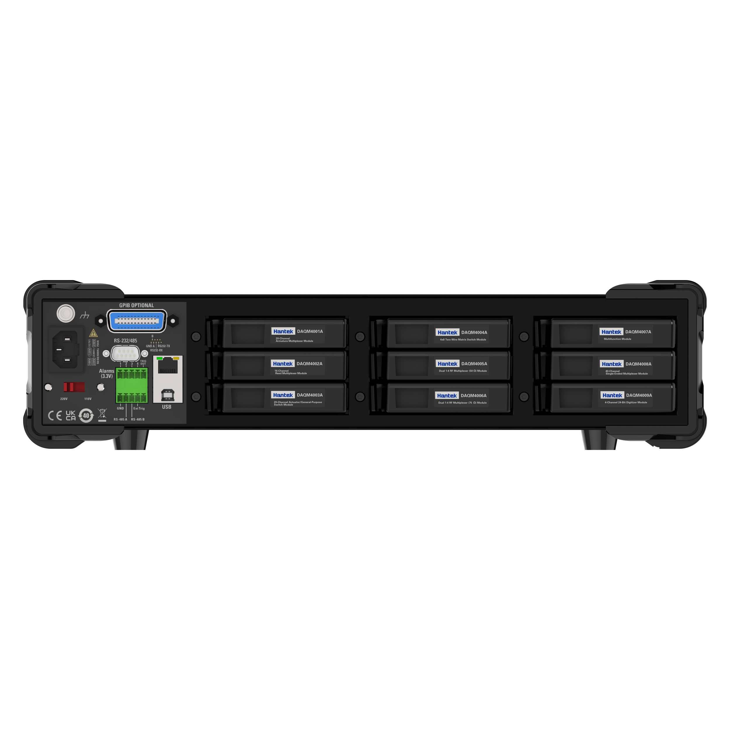
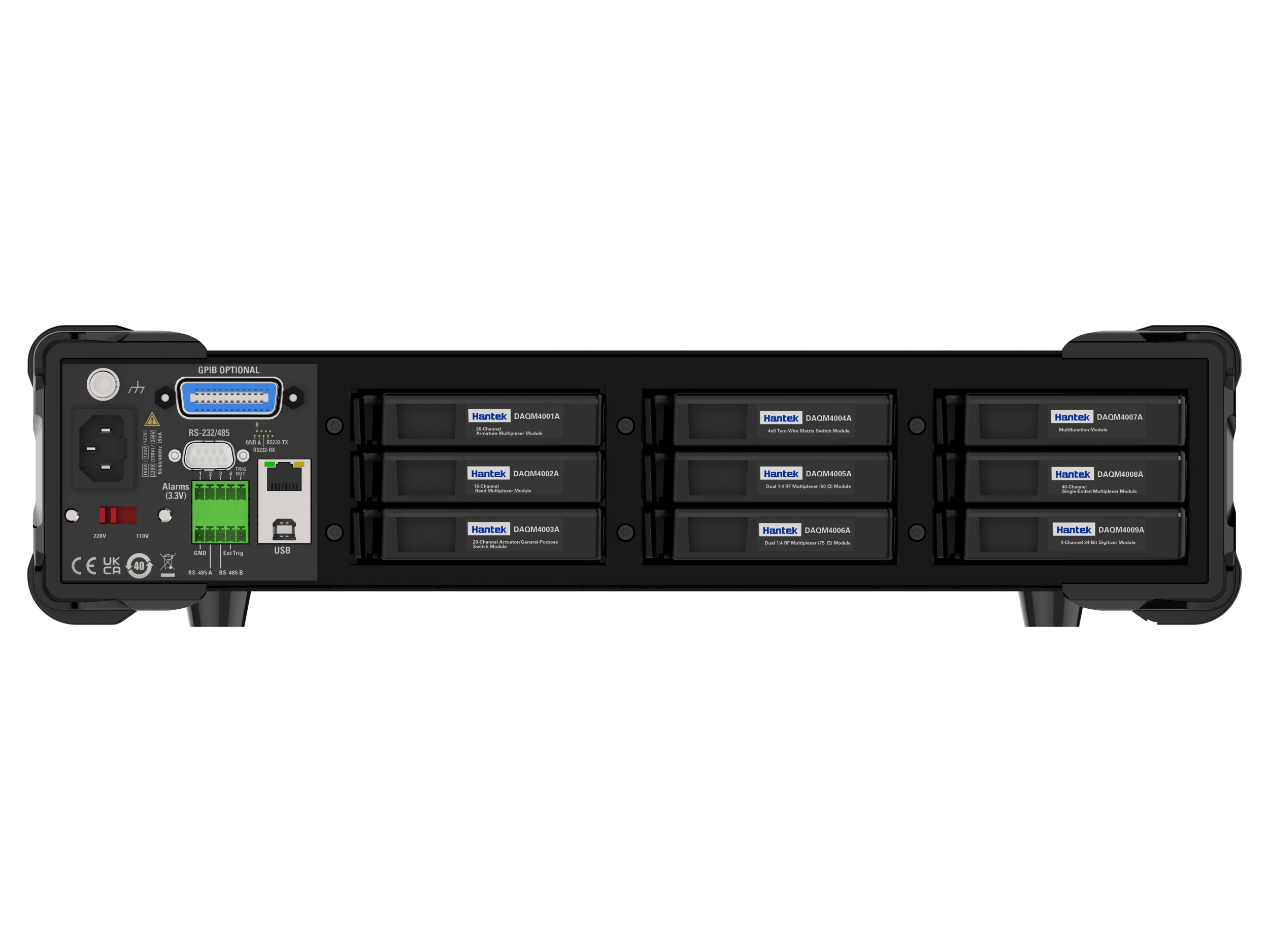
| DAQM4000A |
20 channel multiplexer (solid state relay) * Scan speed up to 450 channels per second * 2-line and 4-line scanning * Built-in cold contact technology 300V switch |
The DAQM4000A is A solid-state relay module that offers two sets (A/B) of 10 2-wire channels each. All 20 channels can be switched to high (HI) and low (LO) inputs, providing fully isolated inputs for a built-in digital meter or external bit. During 4-wire resistance measurements, the channels in group A are automatically paired with those in Group B to provide power and sensing connections. The module has built-in cold contact technology that greatly reduces errors caused by thermal changes when measuring thermocouples. |
| DAQM4001A |
20+2 channel universal multiplexer (armature relay) * Scan speed up to 80 channels per second * 2-line and 4-line scanning * Built-in cold contact technology *300V switch * Additional 2 channels for direct current measurement (1A/CH) |
The DAQM4001A is an integrated multiplexer for general purpose scanning. The same module can mix 2-wire and 4-wire channels; At the same time, an additional 2 current input channels can be used for AC and DC current measurement without the need for external shunt resistors (maximum 1A per channel). The DAQM4001A has a total of 22 channels, intensive multi-function switching and a scan rate of up to 80 channels per second for a variety of data acquisition applications. |
| DAQM4002A |
16 channel high speed multiplexer * Maximum scan rate of 80 channels per second * 2-line and 4-line scanning * Built-in thermocouple reference node |
The DAQM4002A achieves a scan rate of up to 80 channels per second. The module is suitable for high-throughput automated test applications, as well as high-speed data recording and monitoring tasks. 16 two-wire inputs can be switched to 300V. Both 2-wire and 4-wire channels can be mixed on the same module. Current measurement requires the use of the user's own shunt resistor. |
| DAQM4003A |
20 channel actuator/universal switch *SPDT (Type C) self-locking relay *300V, 1A excitation and control |
The DAQM4003A features 20 separate single-pole double-throw (SPDT) relays. It can turn on and off the power supply circuit of the product under test, the control indicator light and the status lamp, and stimulate the external power relay and solenoid. It is combined with matrix and multiplexer modules to form custom switching systems with 300V, 1A contacts that can withstand power up to 50W. |
| DAQM4004A |
4x8 doublet matrix * Switching speed 3ms *32 dual intersections *300V, 1A switch * Up to 96 intersections (3 slots) |
The DAQM4004A module provides the most flexible connection path between the DUT and the test system, allowing different test instruments to connect to multiple points on the DUT simultaneously. The DAQM4004A can connect rows and columns of multiple modules to build larger matrices, such as 8x8, 4x16, etc. Up to 96 intersections can be constructed in a single instrument. |
| DAQM4005A |
Dual 4-channel RF multiplexer (50Ω) *2GHz bandwidth * Includes BNC to SMB adapter cable |
The DAQM4005A provides broadband switching for high frequency and pulse signals. They can be used to route test signals between the device under test and signal generators, oscilloscopes, spectrum analyzers, or other instruments. This module can be used as two independent 1x4 multiplexers, each containing a common shield and a switching center conductor. Connections can be made directly to an SMB input with 2GHz available bandwidth, or to a BNC to SMB adapter that provides 1GHz bandwidth. If the application requires a larger topology, multiple switch groups can also be cascaded to create a 16:1 multiplexer within a single instrument. |
| DAQM4008A |
40 channel single-ended multiplexer * Scan speed up to 80 channels per second * Single-wire switch for public low-end applications |
The DAQM4008A can switch 40 single-wire inputs for each module, such as battery tests, component characteristics, and desktop tests. Low voltage connection and ground isolation, floating up to 300V. The DAQM4008A also supports all 2-wire internal measurements except current. |
| DAQM4014A |
8-channel * Maximum scan rate of 20 channels per second |
DAQM4014A module is continuous current measurement, which can ensure that the current path is disconnected for a short time during the measurement process and does not affect the measured circuit. |
| DAQM4015A |
8-channel * Maximum scan rate of 15 channels per second |
DAQM4015A is a 1500V high voltage measuring card. The maximum input voltage that can be measured is AC1100V/DC1500V, and the current limit is 10mA(1500V). Because the inside of the board has been equivalent to tens of M, in the measured voltage range, there is generally no need to add additional external current limiting measures. |
| DAQM4016A |
8-channel * Maximum scan rate of 15 channels per second |
The DAQM4016A is a 2000V high voltage measuring card. The maximum input voltage that can be measured is AC1500V/DC2000V, and the current limit is 1mA(2000V). Because the inside of the board has been equivalent to tens of M, in the measured voltage range, there is generally no need to add additional external current limiting measures. |
| Range (2) | 24 hours(3) | 90 Day | 1 Year | 2 Year | Temperature coefficient (4) | ||
| TCAL ± 1℃ | TCAL±5℃ | TCAL±5℃ | TCAL±5℃ | ||||
| DC Voltage | |||||||
| 100mV | 0.0030+0.0030 | 0.0040+0.0035 | 0.0050+0.0035 | 0.0065+0.0035 | 0.0005+0.0005 | ||
| 1V | 0.0020+0.0006 | 0.0030+0.0007 | 0.0040+0.0007 | 0.0055+0.0007 | 0.0005+0.0001 | ||
| 10V | 0.0015+0.0004 | 0.0020+0.0005 | 0.0035+0.0005 | 0.0050+0.0005 | 0.0005+0.0001 | ||
| 100V | 0.0020+0.0006 | 0.0035+0.0006 | 0.0045+0.0006 | 0.0060+0.0006 | 0.0005+0.0001 | ||
| 1000V | 0.0020+0.0006 | 0.0035+0.0010 | 0.0045+0.0010 | 0.0060+0.0010 | 0.0005+0.0001 | ||
| True RMS AC Voltage (2, 5, 6) | |||||||
| 100 mV, 1 V, 10 V, 100 V, and 750 V ranges | |||||||
| 5Hz-10Hz | 0.35+0.02 | 0.35+0.03 | 0.35+0.03 | 0.35+0.03 | 0.035+0.003 | ||
| 10Hz-20KHz | 0.04+0.02 | 0.05+0.03 | 0.06+0.03 | 0.07+0.03 | 0.005+0.003 | ||
| 20KHz-50KHz | 0.10+0.04 | 0.11+0.05 | 0.12+0.05 | 0.13+0.05 | 0.011+0.005 | ||
| 50KHz-100KHz | 0.55+0.08 | 0.60+0.08 | 0.60+0.08 | 0.60+0.08 | 0.060+0.008 | ||
| 100KHz-300KHz | 4.00+0.50 | 4.00+0.50 | 4.00+0.50 | 4.00+0.50 | 0.200+0.020 | ||
| Direct Current | Internal Resistance Pressure Drop | ||||||
| 100μA | <0.03V | 0.010+0.020 | 0.040+0.025 | 0.050+0.025 | 0.060+0.025 | 0.0020+0.0030 | |
| 1mA | <0.3V | 0.007+0.006 | 0.030+0.006 | 0.050+0.006 | 0.060+0.006 | 0.0020+0.0005 | |
| 10mA | <0.05V | 0.007+0.020 | 0.030+0.020 | 0.050+0.020 | 0.060+0.020 | 0.0020+0.0020 | |
| 100mA | <0.5V | 0.010+0.004 | 0.030+0.005 | 0.050+0.005 | 0.060+0.005 | 0.0020+0.0005 | |
| 1A | <0.7V | 0.050+0.006 | 0.080+0.010 | 0.100+0.010 | 0.120+0.010 | 0.0050+0.0010 | |
| 3A | <2.0V | 0.180+0.020 | 0.200+0.020 | 0.200+0.020 | 0.230+0.020 | 0.0050+0.0020 | |
| 10A (8) | <0.5V | 0.050+0.010 | 0.120+0.010 | 0.120+0.010 | 0.150+0.010 | 0.0050+0.0010 | |
| True RMS AC Current (2, 6, 9) | |||||||
| 100μA | <0.011v | 3Hz-5KHz | 0.10+0.04 | 0.10+0.04 | 0.10+0.04 | 0.10+0.04 | 0.015+0.006 |
| 5KHz-10KHz | 0.10+0.04 | 0.10+0.04 | 0.10+0.04 | 0.10+0.04 | 0.030+0.006 | ||
| 1mA | <0.11V | 3Hz-5KHz | 0.10+0.04 | 0.10+0.04 | 0.10+0.04 | 0.10+0.04 | 0.015+0.006 |
| 5KHz-10KHz | 0.10+0.04 | 0.10+0.04 | 0.10+0.04 | 0.10+0.04 | 0.030+0.006 | ||
| 10mA | <0.05V | 3Hz-5KHz | 0.10+0.04 | 0.10+0.04 | 0.10+0.04 | 0.10+0.04 | 0.015+0.006 |
| 5KHz-10KHz | 0.10+0.04 | 0.10+0.04 | 0.10+0.04 | 0.10+0.04 | 0.030+0.006 | ||
| 100mA | <0.5V | 3Hz-5KHz | 0.10+0.04 | 0.10+0.04 | 0.10+0.04 | 0.10+0.04 | 0.015+0.006 |
| 5KHz-10KHz | 0.10+0.04 | 0.10+0.04 | 0.10+0.04 | 0.10+0.04 | 0.030+0.006 | ||
| 1A | <0.7V | 3Hz-5KHz | 0.10+0.04 | 0.10+0.04 | 0.10+0.04 | 0.10+0.04 | 0.015+0.006 |
| 5KHz-10KHz | 0.10+0.04 | 0.10+0.04 | 0.10+0.04 | 0.10+0.04 | 0.030+0.006 | ||
| 3A | <2.0V | 3Hz-5KHz | 0.23+0.04 | 0.23+0.04 | 0.23+0.04 | 0.23+0.04 | 0.015+0.006 |
| 5KHz-10KHz | 0.23+0.04 | 0.23+0.04 | 0.23+0.04 | 0.23+0.04 | 0.030+0.006 | ||
| 10A (8) | <0.5V | 3Hz-5KHz | 0.15+0.04 | 0.15+0.04 | 0.15+0.04 | 0.15+0.04 | 0.015+0.006 |
| 5KHz-10KHz | 0.15+0.04 | 0.15+0.04 | 0.15+0.04 | 0.15+0.04 | 0.030+0.006 | ||
| Resistance (7) | Test Current | ||||||
| 100Ω | 1mA | 0.003+0.0030 | 0.008+0.004 | 0.010+0.004 | 0.012+0.004 | 0.0006+0.0005 | |
| 1KΩ | 1mA | 0.002+0.0005 | 0.008+0.001 | 0.010+0.001 | 0.012+0.001 | 0.0006+0.0001 | |
| 10KΩ | 100uA | 0.002+0.0005 | 0.008+0.001 | 0.010+0.001 | 0.012+0.001 | 0.0006+0.0001 | |
| 100KΩ | 10uA | 0.002+0.0005 | 0.008+0.001 | 0.010+0.001 | 0.012+0.001 | 0.0006+0.0001 | |
| 1MΩ | 5uA | 0.002+0.0010 | 0.008+0.001 | 0.010+0.001 | 0.012+0.001 | 0.0010+0.0002 | |
| 10MΩ | 500nA | 0.015+0.0010 | 0.020+0.001 | 0.040+0.001 | 0.060+0.001 | 0.0030+0.0004 | |
| 100MΩ | 500nA | 0.300+0.0100 | 0.800+0.010 | 0.800+0.010 | 0.800+0.010 | 0.1500+0.0002 | |
| Frequency and Period Characteristics | |||||||
| Accuracy:±(%ofreading)(12, 13) | |||||||
| 100 mV, 1 V, 10 V, 100 V, and 750 V (14) | |||||||
| 10Hz-100Hz | 0.03 | 0.03 | 0.03 | 0.03 | 0.035 | ||
| 100Hz-1KHz | 0.003 | 0.008 | 0.01 | 0.01 | 0.015 | ||
| 1KHz -300KHz | 0.002 | 0.006 | 0.01 | 0.01 | 0.015 | ||
| Square Wave (15) | 0.001 | 0.006 | 0.01 | 0.01 | 0.015 | ||
| Additional Gating Time Error ± (% reading) (13) | 1 seconds | 0.1 seconds | 0.01 seconds | ||||
| 3Hz-40Hz | 0 | 0.2 | 0.2 | ||||
| 40Hz-100Hz | 0 | 0.06 | 0.2 | ||||
| 100Hz-1KHz | 0 | 0.02 | 0.2 | ||||
| 1KHz-300KHz | 0 | 0.004 | 0.03 | ||||
| Square Wave (15) | 0 | 0 | 0 | ||||
| Turn-on | |||||||
| 1KΩ | 0.002+0.030 | 0.008+0.030 | 0.010+0.030 | 0.012+0.030 | 0.001+0.002 | ||
| Diode Test | |||||||
| 5V | 0.002+0.030 | 0.008+0.030 | 0.010+0.030 | 0.012+0.030 | 0.001+0.002 | ||
| Temperature characteristics (11) | |||||||
| PT100(DIN/IEC751) | Probe accuracy +0.05℃ | ||||||
| 5 KΩ thermistor | Probe accuracy +0.1℃ | ||||||
| Capacitance (15) | |||||||
| 1.000 nF | 0.50+0.50 | 0.50+0.50 | 0.50+0.50 | 0.50+0.50 | 0.05+0.05 | ||
| 10.00 nF | 0.40+0.10 | 0.40+0.10 | 0.40+0.10 | 0.40+0.10 | 0.05+0.01 | ||
| 100.0 nF | 0.40+0.10 | 0.40+0.10 | 0.40+0.10 | 0.40+0.10 | 0.05+0.01 | ||
| 1.000 μF | 0.40+0.10 | 0.40+0.10 | 0.40+0.10 | 0.40+0.10 | 0.05+0.01 | ||
| 10.00 μF | 0.40+0.10 | 0.40+0.10 | 0.40+0.10 | 0.40+0.10 | 0.05+0.01 | ||
| 100.0 μF | 0.40+0.10 | 0.40+0.10 | 0.40+0.10 | 0.40+0.10 | 0.05+0.01 | ||
.png)

